I recently acquired a antenna analyzer for my amateur radios. I have several different antennas for VHF and UHF frequencies. Amateur radio operators are allowed to operate in the 144 MHz (2 meters) and the 440 MHz (70 cm) bands as well as a number of other frequency bands. A good radio attached to a poor antenna will not be able to reach out and communicate with other radios. Even a mediocre radio attached to a good antenna can work fairly well. One of the more important antenna properties to measure is the standing wave ratio or SWR. It is a measure of how much of the power being transmitted, is reflected back towards the transmitter, by the antenna and cable from the transmitter to the antenna. The ideal SWR would be a 1:1 ratio, but that is almost never achieved. That would mean all of the transmitter power would be transmitted by the antenna. The reflected power should be kept below 3:1, or your transmitter may get damaged.

Antenna Analyzers
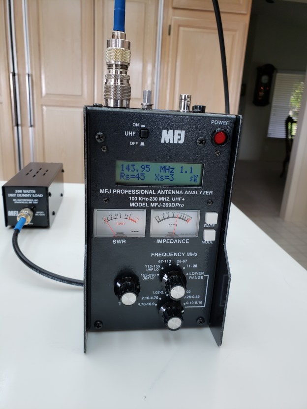
I recently purchased a MFJ-260D antenna analyzer which can analyze frequencies from the low HF (1.8MHz) bands to the UHF (520 MHz) frequencies. This instrument can measure a number of characteristics of antennas and the coaxial cable that attach the antenna to the transceiver. Without an instrument like this, you have no idea of what is going on and cannot make intelligent changes to remedy issues. Since I acquired this instrument I have been able to test several antennas and coaxial cables. You can purchase coax cable from a number of different sources, but you must be careful where you get it from, where it is made, and pay attention to its specifications. I have seen coax cable without any markings on it. Most likely it will be of poor quality. There are no IEEE specifications for manufacturers of coaxial cable. What you want to see is cable made to MIL spec. This means military specifications. All coax cable for amateur radio must be 50 ohms impedance. This is not DC resistance. Impedance is a complex parameter made up of DC resistance, capacitance, and inductance. Impedance is the vector sum of the resistance, capacitance, and inductance of the cable. When I was in college a lot of years ago, we used a slide rule to determine the impedance of a circuit or cable, based upon its characteristics. Of course this was just theoretical at that time. We did not have an instrument like the one above to actually measure the impedance of an antenna or coaxial cable. The picture above is a coaxial cable connected to an antenna analyzer. It is shown connected to a 50 ohm dummy load. You can see the SWR is almost 1:1 and the impedance is 50 ohms. This is rarely achieved with a real antenna. Impedance and SWR can also vary greatly with a number of factors. SWR is the standing wave ratio, which is the ratio of the power, measured in watts, of the power sent out from the transmitter, to the amount of power reflected back to the transmitter. You want to keep this ratio as low as possible. Too much power reflected back to the transmitter will damage the unit. Ideally the ratio should be less than 2:1 and never more than 3:1. This means if three watts is sent out by your radio, one watt is reflected back to the radio. A high SWR will damage your radio. Keep it below 2:1.

Diamond X300na antenna. The antenna is about 9 feet tall and has a gain of 6 dBi on 2 meters and 9 dBi on the 70cm band.
Above is a picture of my 2 meter/70 cm antenna. I have some strict CC&R restrictions where I live and I have not found a permanant location where I can hide my antenna. I have this antenna on a portable mount with LMR 400 coaxal cable attached to it. I usually set it up on Tuesday nights. This antenna works well on frequencies around 2 meters and 70 cm. It has a low SWR and good gain for its size. I an using 40′ of low loss LMR400 coaxial cable to it. The antenna is availale with a SO-239 or an N connector. I chose the N connector because it has a little less signal lost, especially at UHF frequenccies. Signal gain and loss is measured in decibels, or dBi.
Coaxial Cable
There are many different cables available from a number of sources to attach your antenna to your transmitter. Some of these coaxal cables are of good quality and some may not be. An analyzer can help you determine whether a cable is good or poor. Also there are problems that can creep into a good cable that may render it bad, such as moisture or poor connections at the ends of the cable. An antenna analyzer will determine this. An ohmmeter will not. With alternating electricity you are no longer dealing with just resistance, as in direct current; now you are dealing with AC impedance, called reactance, which adds inductance, capacitance, and other properties into the equation. The best cable I have been able to obtain for my 2 meter/70cm radio is LMR 400.
LMR 400 is about the diameter of a little finger and is rather stiff. It is also fairly expensive, running well over $1 per foot. Be careful not to purchase anything cheap that says: like LMR 400 or like RG8X; it must be the real thing. There is a lot of fake things from third world counties out there. LMR400 has a lower dB loss per foot than many other conductors, especially at VHF/UHF frequencies. If you only have a 3 dB loss of signal in your coax, connectors, and your antenna, you have lost 50% of your signal strength before it even gets to the air.
RG8x is also a good cable to run to your antenna in the HF bands. It has more loss at VHF and UHF frequencies than the LMR family, but is less expensive, smaller in diameter, and more flexible. RG8x is a good conductor at lower frequencies. I also use it for jumper cables between equipment.
