

1957 Zenith Radio Chassis
Inside the Zenith Radio With the Speaker Removed
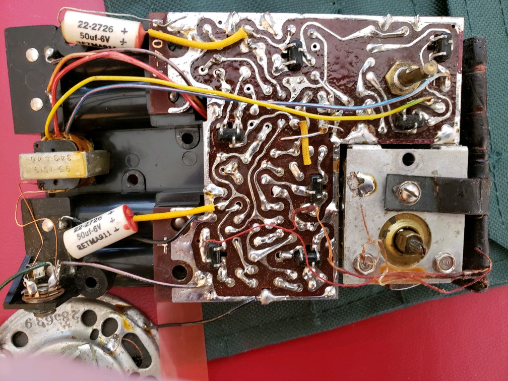
The speaker was removed from the radio to show the components beneath it.
Components
At the middle left is a transformer with 4 different colored wires which drove the speaker. The speaker has been removed to show the PC board and components beneath it. On the lower left, just above the speaker, is an earphone jack. An earphone came with the radios. Just above the speaker and earphone jack is a tubular electrolytic capacitor. It was replaced during the restoration. At the lower right is a large silver tuning capacitor. These tuning capacitors were later replaced with much smaller versions. In the upper right is the bottom of one of the 7 germanium transistor sockets. They are black and standing off the circuit board, with 2 leads down one side and 1 lead off the other side. Since this is a very early transistor radio, the transistors were plugged into sockets. Later they would be soldered directly to the circuit board. Another improvement was the ‘Long Distance’ model which added an 8th transistor to improve the reception of weak stations. The 8th transistor was used as an RF amplifier at the ‘front end’ of the radio. It amplified the signal right off of the antenna. The antenna is the long bar at the far right of the chassis and is connected to the tuning capacitor with a leather strap.
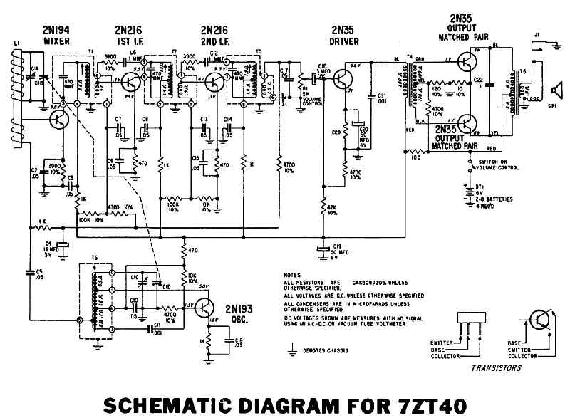
Schematic Electrical Diagram
Tools to Align the Radio
An RF (radio frequency) signal generator and oscilloscope are useful to align the radio for the best performance.
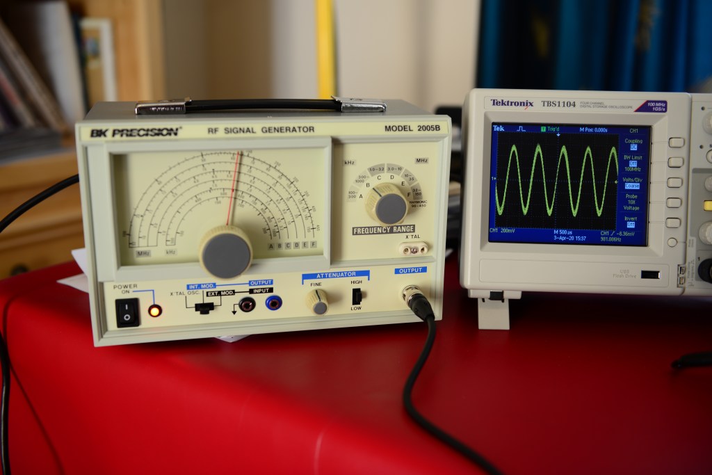
Signal generator and oscilloscope
Radio During the Alignment Procedure
Above is some of the equipment to align the radio. The process involves adjusting several transformers and the tuning capacitor. This process insures the best sensitivity, selectivity, and dial tracking of the radio.
One component that often fails in old radios and televisions are capacitors. (in the old days, they were sometimes called condensers). Old electrolytic capacitors contain a liquid electrolyte that dries out over the years and the capacitors begin to function more like a resistor than a capacitor. Instead of blocking DC voltage, they will begin to ‘leak’ or pass DC voltage. When restoring old radios, bad capacitors must be replaced with modern ones. A good capacitor tester or LCR meter is quite useful in finding bad capacitors. It is very easy to lift the traces on the PC board when removing and replacing components. Use a low temperature with your solder iron.
The IF transformers are peaked at 455 KHz with an oscilloscope and signal generator.
